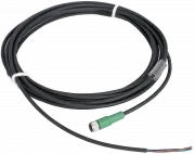
Connect the Power Supply Connector of the light to a power supply source at first (applies to all below-mentioned operating modes).
Apply the voltage of +24 V to pin number 1 (brown wire) and 0 V to pin number 3 (blue wire).
LIGHT OPERATING MODES
PERMANENT ILLUMINATION MODE
For permanent illumination bring the voltage + 24 V to one of the pins numbers 1, 3 or 4 of the Digital and Analogue Input Connector.
The light is ON when the +24 V signal is present. Use a PCL, camera, or another binary signal source.
For the light RGB mode setup and intensity control, please see the text bellow.
LIGHT TRIGGERING MODE
Light triggering mode saves energy and extends the lifetime of the light.
Trigger operation mode is recommended when a parallel operation of 2 or more lights might affect the quality of the acquired image.
To start using a triggering mode, bring one of the pins number 1, 3 or 4 of the Digital and Analogue Input Connector to +24 V. The light is ON
when the +24 V signal is present.
Use a PCL, camera, or another binary signal source for triggering. For the light RGB mode setup and intensity control, please see the text bellow.
RGB OPERATION MODE SETUP & LIGHT INTENSITY REGULATION
DIGITAL MODE - There are 3 "banks" (memories) in the RGB light, which are used to store the desired light output colour.
Applying a voltage of +24 V to one of the 3 inputs of the Digital and Analogue Input Connector the pre-saved RGB colour is activated.
ANALOGUE MODE - The colour of the output light might be setup by analogue voltage or current in the range of either 0 V to +10 V or 0-20 mA.
The colour scheme applies in the range of 0-360° according to the HSI colour space.
By applying +24 V to pin number 3 (blue wire) of the Digital and Analogue Input Connector, the light will turn on when the +24 V signal is present.
Configuration
| Model series | Wavelength | Datasheet | 2D drawing | 3D model |
|---|---|---|---|---|
|
SP-35RGB
(More variants)
|
RGB |
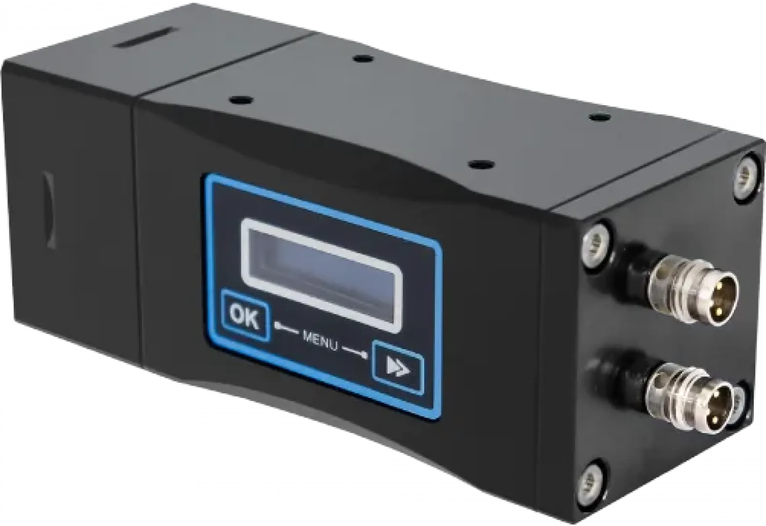
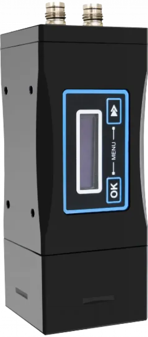
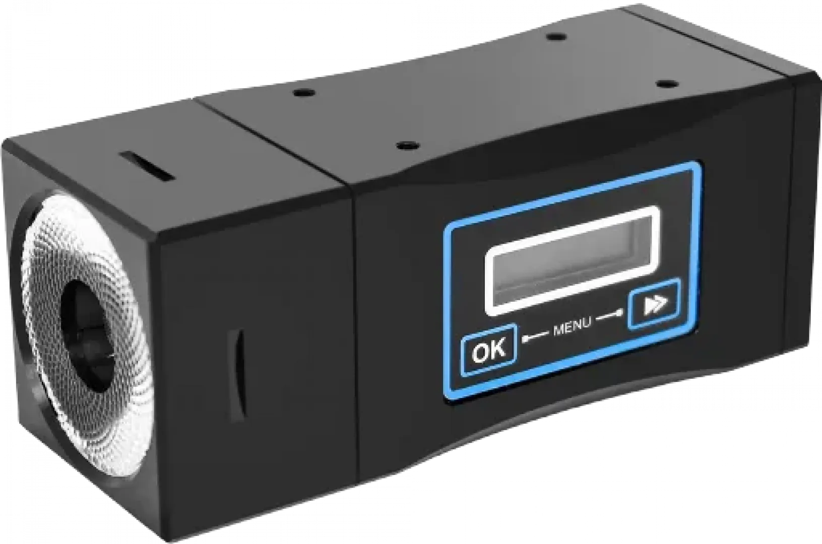
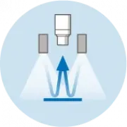
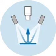
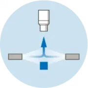
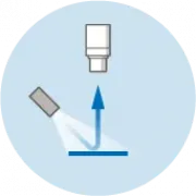
Principles of use
Dimensions and weights
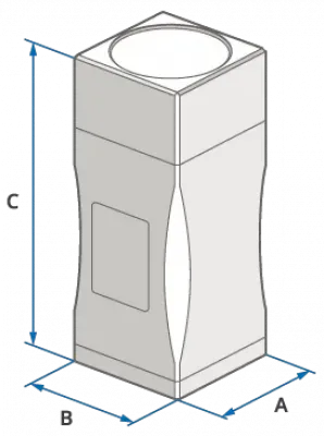
| Model series | A - Length (mm) | B - Width (mm) | C - Height (mm) | Weight (g) |
|---|---|---|---|---|
| SP-35RGB | 40 | 40 | 100 | 240 |
No question has been asked yet.
Your questions
You must log in to post questions.