LIGHT OPERATING MODES
PERMANENT ILLUMINATION MODE
This light is designed for both the permanent and light-triggering mode.
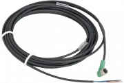
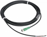
For permanent illumination bring the voltage of 12-24 V to the pin number 4 (black wire).
The light is ON during the time when the 24 V EN signal is activated.
Use a PCL, camera or another binary signal source.
For the light intensity control, please see the text bellow.
LIGHT TRIGGERING MODE
Light triggering mode saves energy and extends the lifetime of the light.
Trigger operation mode is recommended when a parallel operation of 2 or more lights might affect
the quality of the acquired image.
To start using a triggering mode, bring the pin number 4 (black wire) to a 12-24 V signal.
The light is ON when a voltage signal is present at pin number 4 then.
Use a PCL, camera, or another binary signal source for triggering.
For the light intensity control, please see the text bellow.
STROBE MODE
Strobe function significantly multiplies the maximum intensity of the light.
The strobing function saves energy, extends the light lifetime and in many cases improves the stability of the entire inspections system.
Pin number 2 (white wire) of the M8 connector is used to activate the strobe function.
The maximum strobe pulse time is 10 ms, while the light idle time must be at least 10 times longer, which in this case makes 100 ms.
Bringing a permanent logical 1 signal (12-24 V voltage) to a light strobe input, the light standardly operates in a 10 ms ON and 100 ms OFF cycle.
The strobe operation pulse might be chosen in the time span of 1-10 ms.
Please do not use a trigger mode during strobing function, do not bring a voltage to the pin number 3.
LIGHT SOURCE INTENZITY REGULATION
The light intensity might be regulated analogue voltage,
PWM signal or an external controller.
In case of using an analogue signal, the light intensity might be regulated in a linear way at a pin number 4
by the voltage span of 2.7 -10 V.
Bringing a voltage of 12-24 V to the pin number 4, the light works at its maximum intensity.
The maximum PWM frequency is ≤ 40 kHz.
Configuration
| Model series | Wavelength | Datasheet | 2D drawing | 3D model |
|---|---|---|---|---|
|
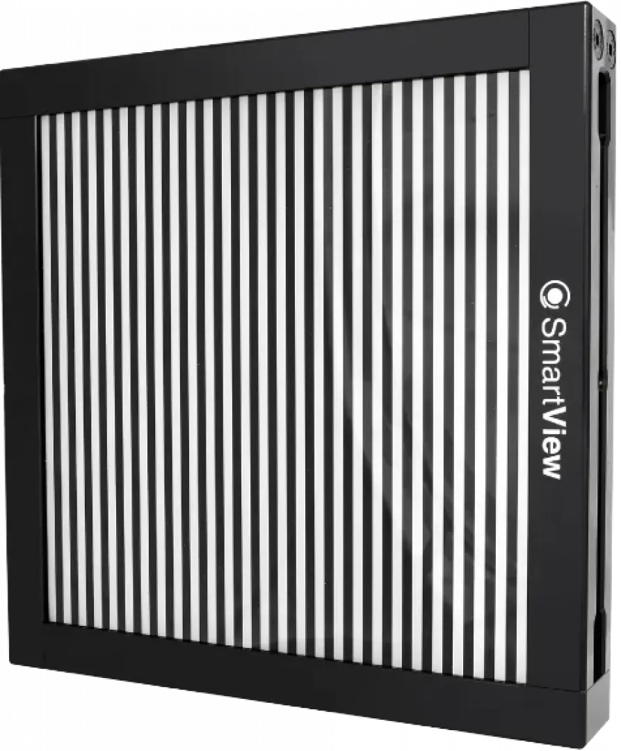
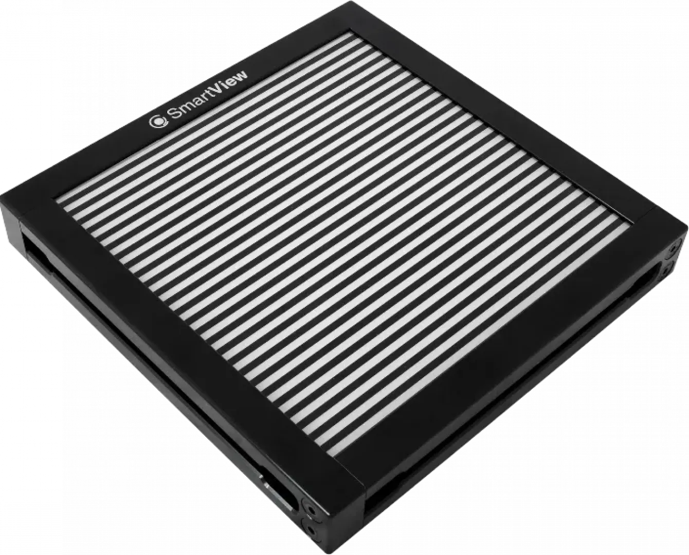
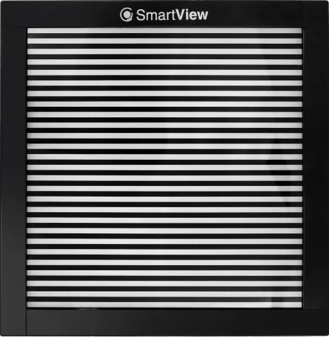
FLDB-320B-1515
(More variants)
|
470 |
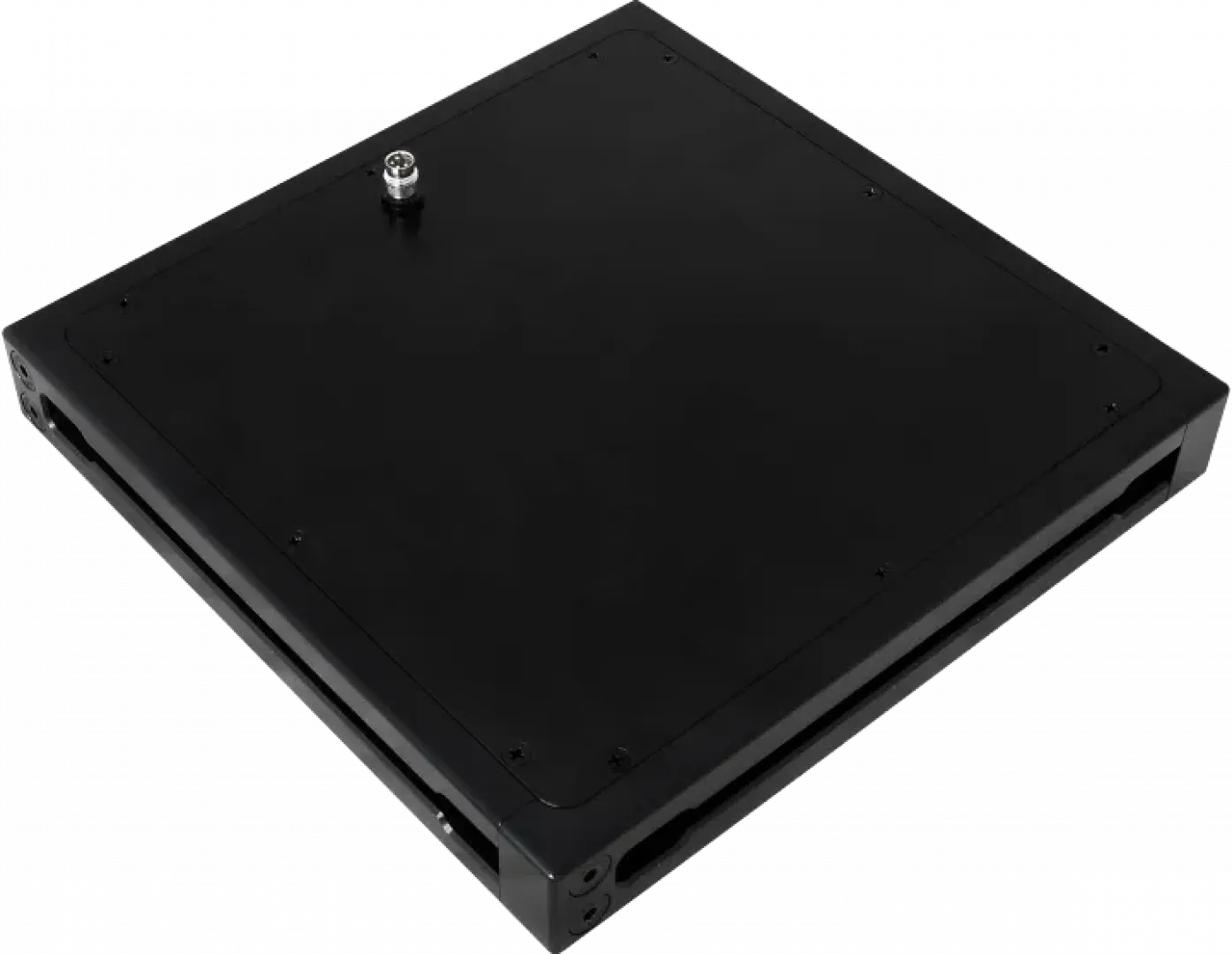
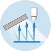
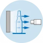
Principles of use

Dimensions and weights
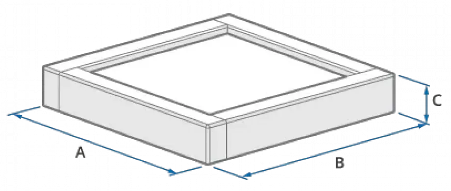
| Model series | A - Length (mm) | B - Width (mm) | C - Height (mm) | Weight (g) |
|---|---|---|---|---|
| FLDB-320B-1515 | 352 | 352 | 28 | 3100 |
No question has been asked yet.
Your questions
You must log in to post questions.